Great Tips About What Are The 8 Types Of Logic Gates
Unlocking the Secrets of Logic Gates
Ever wondered how your computer, smartphone, or even that fancy coffee maker works its magic? A big part of the answer lies in tiny components called logic gates. These aren't the kind of gates you find in a fence; instead, they're fundamental building blocks of digital circuits, deciding whether a signal passes through or not based on certain rules. Think of them as the traffic controllers of the digital world, directing the flow of information.
1. What exactly are these "logic gates," then?
At their core, logic gates perform basic logical operations on one or more input signals to produce a single output. This output is always either true (represented as 1) or false (represented as 0). It's a binary world in there! They make decisions based on the combination of inputs they receive. It's like saying, "If this AND that are true, then do this!" (That's actually one type of logic gate!).
These gates are constructed using transistors, which act like tiny electronic switches. The arrangement of these transistors determines the specific logic operation the gate performs. And don't let the complexity scare you. The concept is actually pretty easy to grasp once you get familiar with the different types.
So, how many of these digital decision-makers are out there? Well, let's talk about the common ones. While there are technically more, we'll focus on the core eight types that form the bedrock of digital electronics. Get ready to meet your new digital friends!
The All-Star Lineup
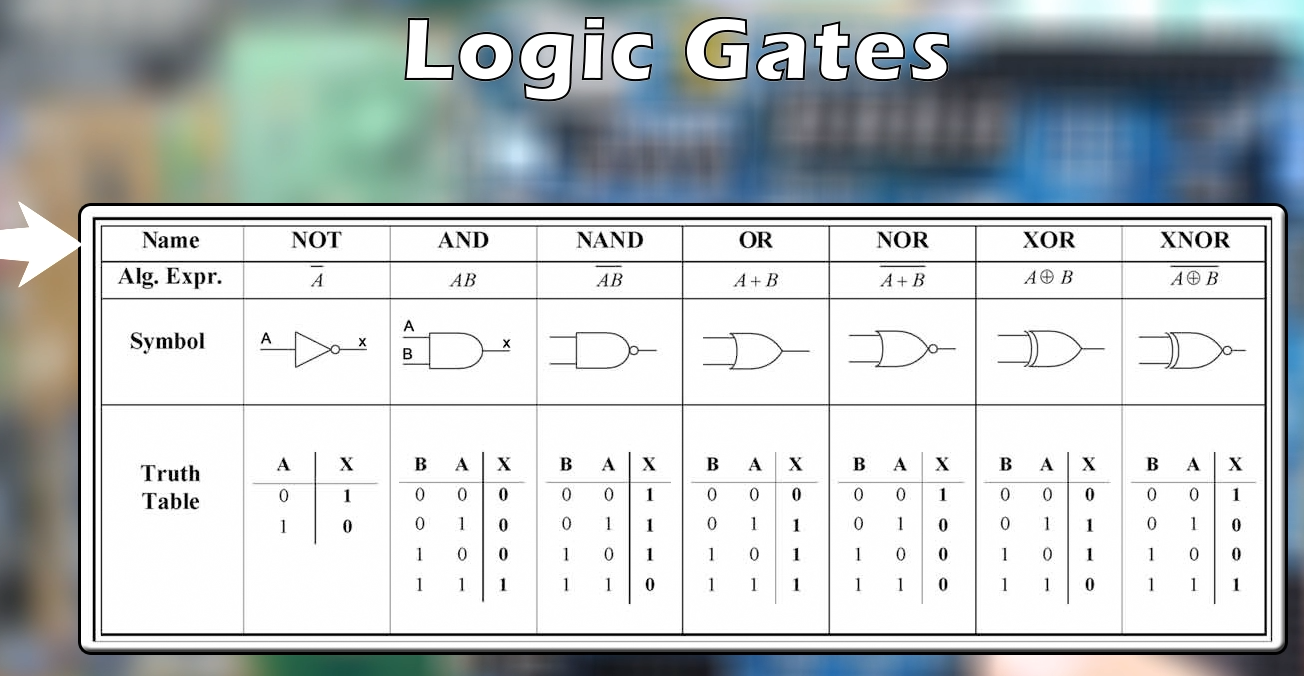
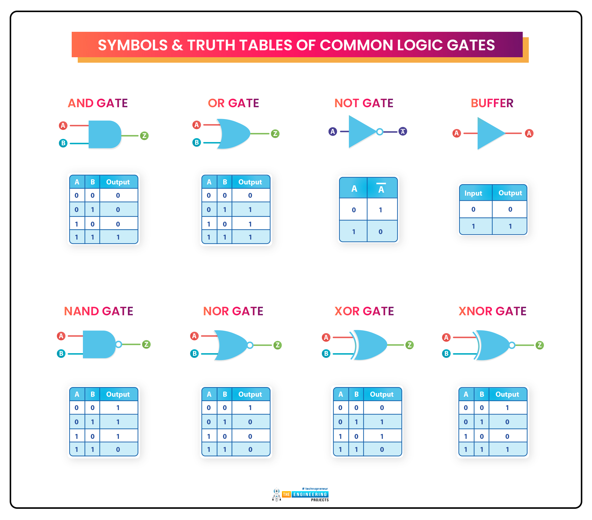
Alright, let's dive into the heart of the matter! Here's a breakdown of the eight fundamental logic gates, each with its own unique personality and function. We'll explore their truth tables (which show their behavior for all possible input combinations) and a simple explanation to help you understand how they work. No need to worry, we'll keep it accessible!
2. 1. The AND Gate
The AND gate is a bit of a stickler. It only outputs "true" (1) if all of its inputs are also true (1). If even one input is false (0), the output is false. Think of it like needing a key and a password to unlock a door; if you're missing either one, you're not getting in.
Truth Table:
Input A | Input B | Output
------- | ------- | ------
0 | 0 | 0
0 | 1 | 0
1 | 0 | 0
1 | 1 | 1This gate is crucial for situations where multiple conditions must be met for something to happen. Consider a sensor system that requires both temperature and pressure to be within a certain range before triggering an alarm.
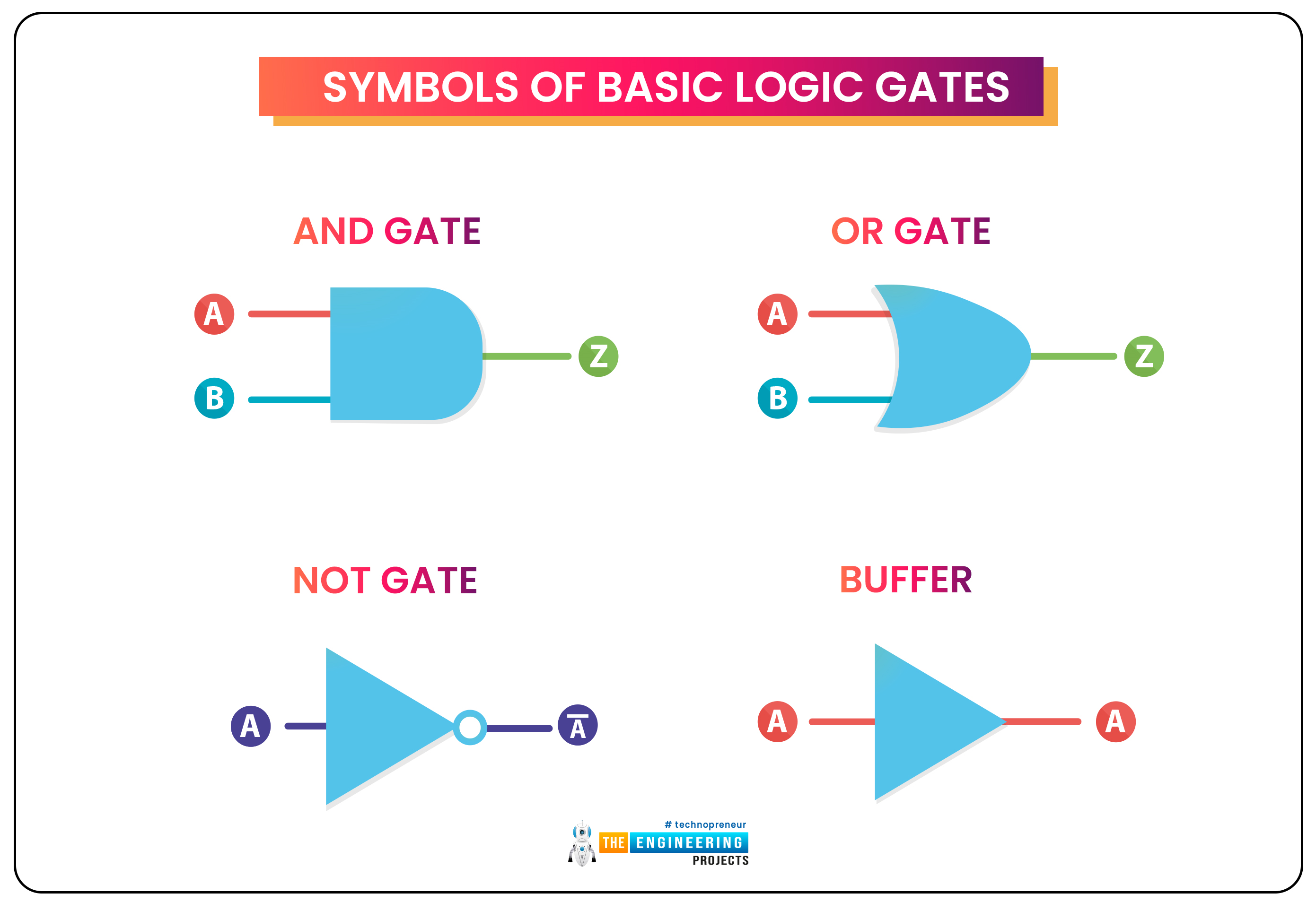
Its symbol looks like a D-shape, with the inputs on the flat side and the output on the curved side. Keep an eye out for it!
3. 2. The OR Gate
The OR gate is far more lenient than the AND gate. It outputs "true" (1) if at least one of its inputs is true (1). It only outputs "false" (0) if all of its inputs are false (0). It's like saying you need either a ticket or an invitation to get into a party.
Truth Table:
Input A | Input B | Output
------- | ------- | ------
0 | 0 | 0
0 | 1 | 1
1 | 0 | 1
1 | 1 | 1OR gates are perfect for situations where any one of several conditions being true is enough to trigger an action. Imagine a car alarm that activates if either the door is opened or the window is broken.
The OR gate symbol looks like a crescent moon pointing to the right. It's a softer shape compared to the AND gate.
4. 3. The NOT Gate
The NOT gate is the simplest of the bunch, with only one input. It inverts the input. If the input is "true" (1), the output is "false" (0), and vice versa. It's like a "reverse" button for your digital signals.
Truth Table:
Input A | Output
------- | ------
0 | 1
1 | 0NOT gates are incredibly useful for creating the opposite of a signal or condition. For example, if you want something to happen only when a sensor isn't detecting something, you'd use a NOT gate.
Its symbol is a triangle with a small circle at the output. That little circle is your clue that it's a NOT gate.
5. 4. The NAND Gate
The NAND gate is a combination of the AND and NOT gates. It outputs "false" (0) only if all of its inputs are true (1). Otherwise, it outputs "true" (1). Think of it as the opposite of the AND gate. It is called "Not AND".
Truth Table:
Input A | Input B | Output
------- | ------- | ------
0 | 0 | 1
0 | 1 | 1
1 | 0 | 1
1 | 1 | 0NAND gates are incredibly versatile because they can be used to create any other type of logic gate. In fact, many digital circuits are built entirely from NAND gates!
Its symbol looks like an AND gate with a small circle at the output, signifying the negation.
6. 5. The NOR Gate
Similar to the NAND gate, the NOR gate combines the OR and NOT functions. It outputs "true" (1) only if all of its inputs are false (0). Otherwise, it outputs "false" (0). It is called "Not OR".
Truth Table:
Input A | Input B | Output
------- | ------- | ------
0 | 0 | 1
0 | 1 | 0
1 | 0 | 0
1 | 1 | 0NOR gates are useful for creating circuits that activate only when none of several conditions are true. Imagine a system that only starts up when all safety checks have passed (and therefore, no errors are present).
Its symbol looks like an OR gate with a small circle at the output, indicating the negation.
7. 6. The XOR Gate
The XOR (Exclusive OR) gate outputs "true" (1) if exactly one of its inputs is true (1). If both inputs are the same (both true or both false), the output is "false" (0). It's like saying you can have either cake or ice cream, but not both!
Truth Table:
Input A | Input B | Output
------- | ------- | ------
0 | 0 | 0
0 | 1 | 1
1 | 0 | 1
1 | 1 | 0XOR gates are commonly used in circuits for comparing bits and performing addition. They're essential in many types of digital computation.
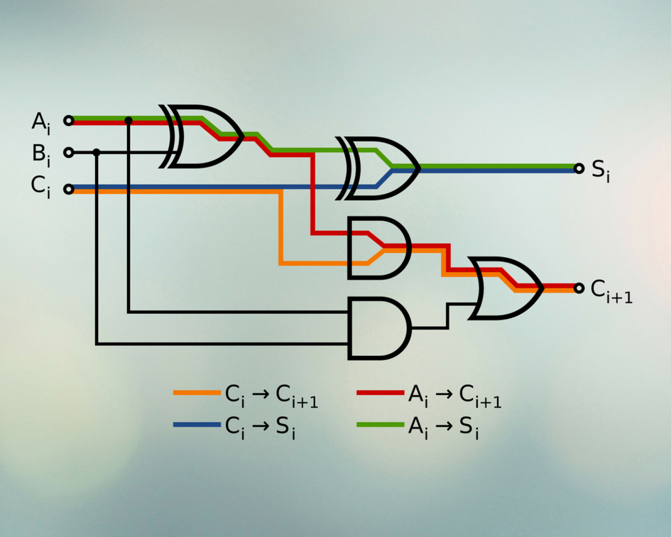
The XOR symbol looks like an OR gate with an extra curved line before the inputs.
8. 7. The XNOR Gate
The XNOR (Exclusive NOR) gate is the opposite of the XOR gate. It outputs "true" (1) if both inputs are the same (both true or both false). If the inputs are different, the output is "false" (0). It's useful for finding equivalency between two inputs.
Truth Table:
Input A | Input B | Output
------- | ------- | ------
0 | 0 | 1
0 | 1 | 0
1 | 0 | 0
1 | 1 | 1XNOR gates are often used in circuits that need to check for equality. For example, verifying if two data signals are identical.
Its symbol looks like an XOR gate with a small circle at the output, signifying the negation.
9. 8. The Buffer Gate
The Buffer gate might seem simple, but it serves an important purpose. It simply passes the input signal to the output without modification. If the input is "true" (1), the output is "true" (1), and vice versa.
Truth Table:
Input A | Output
------- | ------
0 | 0
1 | 1So, why use it? Buffer gates are primarily used to strengthen a weak signal or to isolate one part of a circuit from another. They act like a signal amplifier, ensuring the signal remains clear and strong as it travels through the circuit.
The symbol is a triangle, similar to a NOT gate, but without the circle at the output.

Different Types Of Logic Gates With Truth Table, Expression ETechnoG
Why Are Logic Gates Important? (And Why Should You Care?)
Now that you've met the key players, you might be wondering why all this matters. Well, logic gates are the fundamental building blocks of all digital devices. Everything from your phone to your car to your washing machine relies on these tiny switches making decisions based on logic.
10. The Foundation of Modern Computing
Without logic gates, we wouldn't have computers, smartphones, the internet, or any of the digital technologies that have transformed our world. They enable us to perform complex calculations, store and retrieve information, and control machines with incredible precision.
Think of a calculator. Every time you press a button, logic gates are working behind the scenes to perform the calculation and display the result. Or consider a traffic light. Logic gates control the timing and sequencing of the lights, ensuring a smooth flow of traffic.
Understanding logic gates provides a foundational understanding of how these technologies work at their most basic level. While you don't need to be an electrical engineer to appreciate their importance, having a grasp of the concept can give you a new perspective on the digital world around you.
So, the next time you use your smartphone or turn on your computer, remember the tiny logic gates working tirelessly inside, making it all possible!
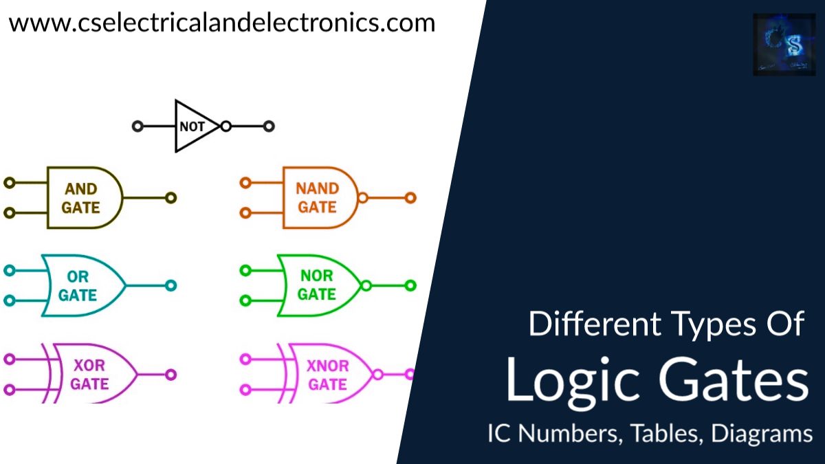
Different Types Of Logic Gates, IC Numbers, Tables,
Logic Gates in Action
Okay, enough theory! Let's see how these logic gates are used in practical applications. You'll find them in everything from simple circuits to complex microprocessors.
11. Everywhere You Look
In alarm systems, AND gates might be used to trigger an alarm only when both a door sensor and a window sensor are activated. This prevents false alarms caused by a single sensor malfunction.
In computer memory, logic gates are used to store and retrieve data. Flip-flops, which are circuits built from logic gates, can hold a single bit of information (0 or 1).
In control systems, logic gates can be used to automate processes. For example, a robotic arm might use logic gates to determine the next action based on sensor readings.
Even in your everyday appliances, like a washing machine, logic gates control the timing and sequencing of the different cycles. They ensure that the water fills at the right time, the clothes are washed for the correct duration, and the water drains properly.
Frequently Asked Questions (FAQs) About Logic Gates
Still have some questions buzzing around? Here are a few frequently asked questions to help clear things up!
12. Q
A: Absolutely! You can experiment with building simple logic gates using transistors, resistors, and other electronic components. There are plenty of online tutorials and projects that can guide you through the process. It's a great way to get hands-on experience and deepen your understanding of how they work. However, building complex circuits requires specialized knowledge and tools.
13. Q
A: Yes, while we've primarily discussed logic gates with two inputs, it's possible to have gates with three, four, or even more inputs. For example, you might have a three-input AND gate that requires all three inputs to be true for the output to be true. The basic principles remain the same; the gate simply evaluates a larger number of inputs.
14. Q
A: There are numerous resources available online, including websites, tutorials, and online courses. Many universities also offer introductory courses in digital logic design as part of their electrical engineering or computer science programs. A simple search for "digital logic design tutorial" will turn up a wealth of information to get you started. You can also check out textbooks and online forums dedicated to electronics and digital circuits.
